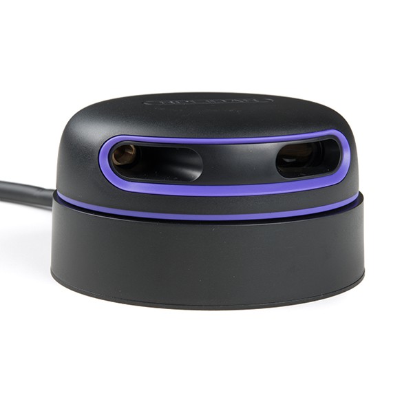
3D scanning head with 2D lidar
I built a DIY 3D scanning system that converts a 2D lidar into a 3D scanner using a rotating servo mechanism. The project includes custom firmware for AVR and STM32 microcontrollers, real-time visualization tools, and a complete software stack for processing and synchronizing lidar data. Features include IMU integration for improved accuracy and movement tracking.
Tech: C++, Go, Embedded C, RPlidar, Atmega328p, MPU-6050 / MPU-9250, STM32
Tags: 10k lines of code,
Robotics,
3D scanning
Source: https://github.com/dsonyy/lidar-2d-to-3d
The goal of this project was to create a device that can scan its surroundings in 3D using a 2D lidar.
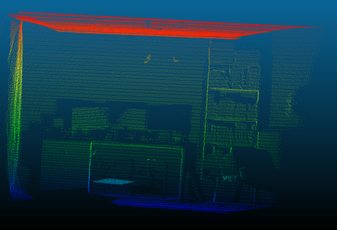
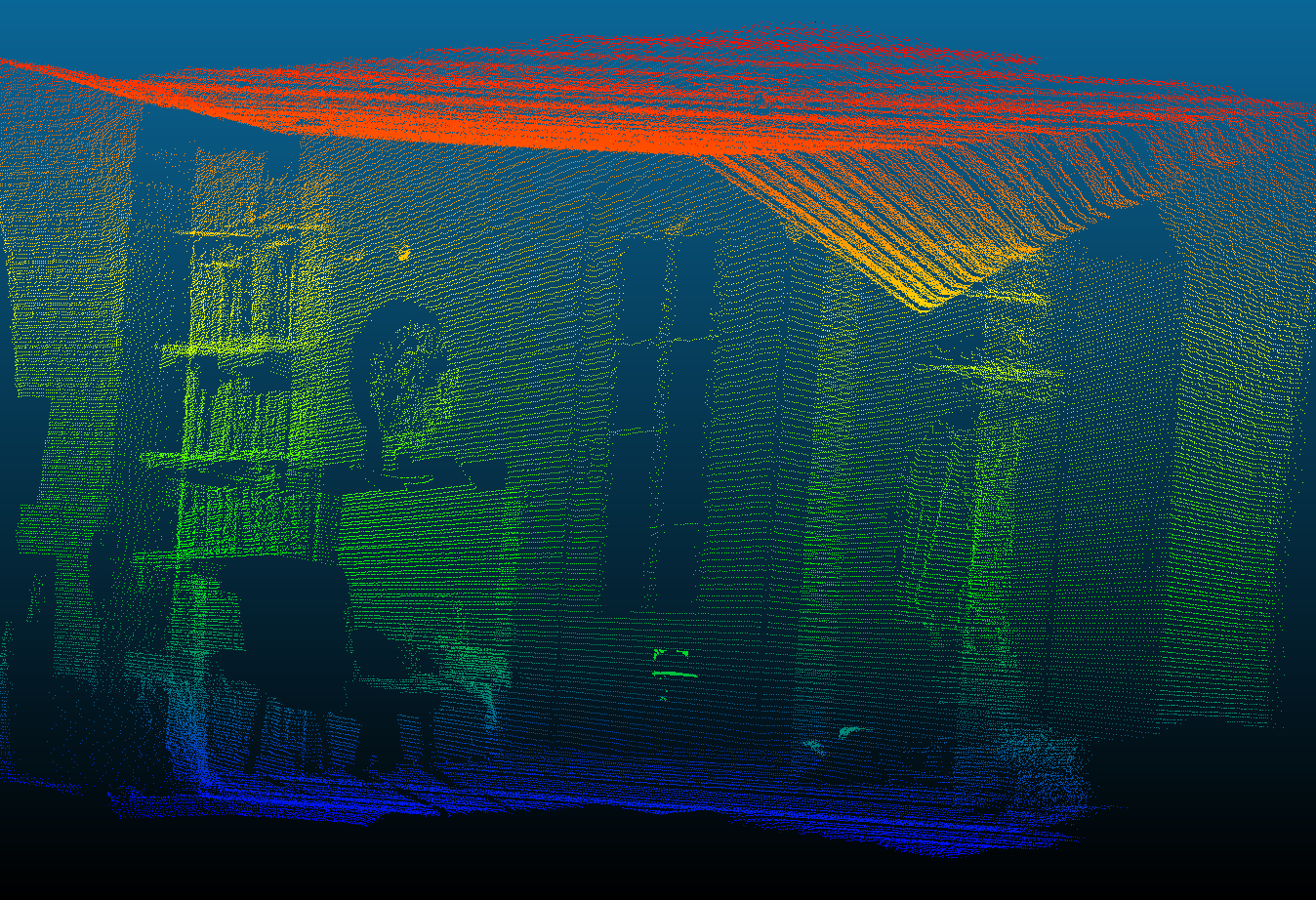
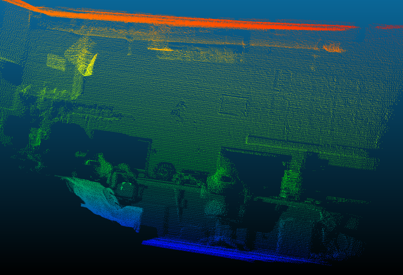
Gallery
3D


2D
Submodules
This repository combines several repositories with the prefix lidar- developed under KNEI that are related to 3D scanning. You can find more information about each project in their README files.
The asterisk * marks repositories that are required for 3D scanning. The other projects can be useful when working with 2D scanning.
lidar-tools*
A collection of tools useful when working with the lidar.
sync*
The most important of the tools. Its tasks include:
- Establishing connection with the microcontroller (which controls the servo and accelerometer) and the lidar
- Synchronizing data/measurements from available sources
- Calculating 3D point cloud points
- Printing point by point (x, y, z) to standard output (stdout)
servoctl
Sends a data frame to the microcontroller to set the servo to a given position.
transmitter/receiver
Sends/receives 2D lidar data (obtained e.g. using lidar-scan) via UDP.
scan-dummy
Pretends to be lidar-scan. Generates sample data.
Authors: Szymon Bednorz, Bartek Pacia
lidar-avr*
Software designed to be flashed onto the AVR Atmega328p microcontroller, which handles the servo and accelerometer and communicates via USART with the operator’s device.
More details about the exact configuration and operation can be found in later sections of this document.
Authors: Szymon Bednorz, Bartek Pacia
lidar-scan*
A project derived from lidar-visualizations. The idea was to create a program that does one thing and does it well.
The program’s task is to establish a connection with the lidar and print received data in text form to standard output (stdout). The data can then be passed to any other program that understands the input data format.
Compatible with Linux, macOS, and Windows systems.
Example output:
# A comment
# ! ID Number   Elapsed time [ms]
# Angle [°]   Distance [mm]
! 0 0
120  100
240  100
360  100
! 1 500
120  200
240  200
360  200
! 2 500
Authors: Szymon Bednorz, Bartek Pacia
lidar-vis
Graphically displays data received from the lidar using lidar-scan.
A project derived from lidar-visualizations. It’s a “sister” program to _lidar-scan - does one thing and does it well.
Compatible with Linux, macOS, and Windows systems.
Authors: Szymon Bednorz, Bartek Pacia
lidar-visualizations
Displays lidar data in text or graphic form in real-time.
The software has changed its form almost completely several times. It was created for an article in “Elektronika Praktyczna”. Currently, it’s not actively developed. The code consists of several interfaces that theoretically allow for creating additional functionality. The program uses the official RPLIDAR SDK and the high-level SFML graphics library.
Compatible with Linux, macOS, and Windows systems.
More information can be found in the article “Visualization of LIDAR Scanner Measurements” in “Elektronika Praktyczna” from March 2021.
Author: Szymon Bednorz
lidar-stm32
An interesting project that, like lidar-visualizations, was created for “Elektronika Praktyczna”. It runs on an STM32 board, which sends/receives data to/from the lidar via UART and then visualizes it.
The RPLIDAR SDK is not adapted for embedded devices, so an original implementation for STM32 was created based on it.
More information can be found in the article “Visualization of LIDAR Scanner Measurements” in “Elektronika Praktyczna” from March 2021.
Author: Bartek Dudek
Components
Lidar
The lidar used in the project is Slamtec RPLIDAR A3. The manufacturer also provides RPLIDAR SDK supporting Linux, macOS, and Windows systems, which allows working with the hardware.
The lidar has its own power supply. It also has a USB cable to send data to the operator’s device.
Specification
| Parameter | A3 |
|---|---|
| Measurement range | up to 25m |
| Measurement frequency | up to 16kHz |
| Point cloud frequency | 5Hz - 20Hz |
| Angular resolution | up to 0.225° |
| Communication interface | TTL UART |
| Communication speed | 256000bps |
Sources
Scanning Modes
RPLIDAR offers several scanning modes. Only two are worth noting: default sensitivity (indoor) and stability (outdoor). When working outside, especially on very sunny days, you can clearly see the difference in the number of correctly performed measurements. The other modes exist for backward compatibility with previous generations of the device and/or require lower baudrate during data transmission.
| ID | Scan mode | Sample time [us] | Frequency |
|---|---|---|---|
| 0 | Standard | 252 | 0.484406 |
| 1 | Express | 126 | 0.968812 |
| 2 | Boost | 63 | 1.93762 |
| 3 | Sensitivity/Indoor (default) | 63 | 1.93762 |
| 4 | Stability/Outdoor | 100 | 1.2207 |
Data
- The default format of lidar data is pairs (angle, distance) in units [degrees, millimeters].
- Measurement pairs are grouped by 360 degrees - one point cloud.
- If a measurement for a given angle fails, the distance value is 0.
- The maximum number of points in one cloud is 8192, which is a limitation set by the manufacturer.
- The number of points in a cloud - 360 degrees - depends on the scanning mode and the number of revolutions per minute (RPM). The slower the rotation speed, the more points in the cloud. The recommended operating range is from 200 to 1023 rpm. At values lower than 200, there is a risk of exceeding 8192 points per cloud, which can cause problems. The default value is 660 rpm.
Lidar Motor Speed Measurements
| Software RPM | Measured RPM | Software RPS | Measured RPS | Error |
|---|---|---|---|---|
| 200 | 196.62 | 3.33 | 3.28 | ~1.7% |
| 400 | 432.02 | 6.67 | 7.20 | ~8.0% |
| 600 | 684.52 | 10.00 | 11.41 | ~14.0% |
| 800 | 965.14 | 13.33 | 16.09 | ~20.6% |
| 1000 | 1268.98 | 16.67 | 21.15 | ~26.8% |
General Lidar Results Measurements
Scanning mode: Sensitivity
| Target RPM | Total time [s] | Points | Points per cloud | Clouds | Avg. time per cloud [s] | Measured RPM |
|---|---|---|---|---|---|---|
| 200 | 28.369 | 447133 | 4860.14 | 92 | 0.31 | 194.58 |
| 400 | 28.187 | 444097 | 2198.50 | 202 | 0.14 | 429.99 |
| 600 | 28.308 | 446794 | 1387.56 | 322 | 0.09 | 682.49 |
| 660* | 28.378 | 448529 | 1274.23 | 352 | 0.08 | 744.24 |
| 800 | 26.792 | 423121 | 984.00 | 430 | 0.06 | 962.97 |
| 1000 | 27.327 | 432130 | 748.93 | 577 | 0.05 | 1266.88 |
* default
Servo
The servo is responsible for rotating the plane that is scanned by the lidar. It is controlled by a PWM signal using the microcontroller.
It requires its own power supply.
IMU
IMU (Inertial Measurement Unit) is a device used for inertial navigation equipped with an accelerometer and gyroscope. The system we use is MPU-6050 with 6 degrees of freedom (accelerometer X, Y, Z and gyroscope X, Y, Z). In the initial phase of project development, it was noticed that a construction consisting of just the lidar and servo could be prone to inaccuracies caused by:
- the construction could be tilted more or less in any direction during scanning
- the servo we use has limited accuracy
Both problems were meant to be solved by the IMU, which would provide real-time data about the current tilt/rotation of the scanning plane.
Unfortunately, results using the described IMU and plane rotation estimation methods turn out to be even more inaccurate than using just the lidar and servo. The reasons should be sought in position estimation, which involves continuously updating the state based on previous measurements. In this way, the error grows very quickly, which means that two scans of the same scene can differ significantly from each other.
The final version of the project is prepared to work with and without IMU. For better results, it is recommended not to use IMU. If you plan to move the construction during scanning, you can decide to use it, although you will then have to deal with growing error.
MPU-6050
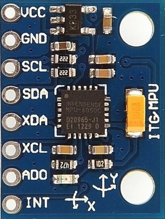
The basic functionality of the device is using a 3-axis accelerometer and gyroscope. In this way, we receive a stream of raw measurements consisting of six 2-byte floating-point numbers in the scale described in the documentation. The module communicates via I2C interface.
MPU-6050 in i2cdevlib database
MPU-9250
A module completely compatible with MPU-6050. The difference is that it has an additional 3-axis magnetometer, which requires special calibration. The magnetometer is currently not used in the project.
Calibration
MPU-6050 calibration involves placing it on a surface as flat as possible, performing a series of measurements (6 values per measurement), calculating their average, and saving the results. The gravitational acceleration should also be taken into account, which should be clearly visible on one of the axes. The calibration results should be added to each subsequent measurement with the appropriate sign.
The lidar-tools/sync program performs calibration automatically before starting scanning (if we use IMU).
DMP
An interesting part of MPU is the DMP (Digital Motion Processor) module, which the manufacturer boasts about, but at the same time official documentation completely omits its existence. On the internet, you can find numerous unofficial discussions and libraries trying to use its functionality. One of many (including still undiscovered) functionalities is rotation estimation based on raw data (calculating quaternion).
Microcontroller
The microcontroller used in the project is ATmega328p. The software that must be on it is in the lidar-avr repository. It is responsible for:
- controlling the PWM signal to control the servo
- communication via I2C with MPU-6050 (or MPU-9250)
- communication with the operator’s computer (receiving/sending data frames)
Details about wire connections and project components can be found in the hardware section (an Arduino UNO board was used, but the microcontroller is programmed directly).
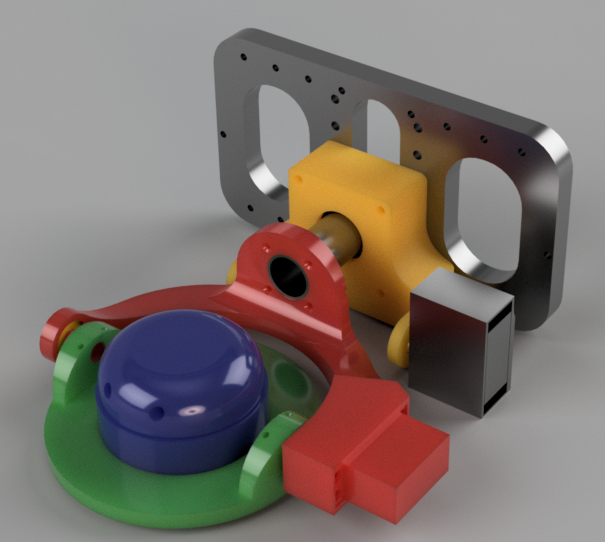
Scanning Head
The mechanical construction on which the individual project components are mounted.
Prototype
Final Version
The construction was designed in Autodesk Fusion 360 and printed using 3D technology.
3D Scanning
3D scanning involves collecting data from several sources and combining them in a way to get information about the surroundings.
The most important device is the lidar, which when started can generate several point clouds per second. Points are represented as pairs (angle, distance) in units [degrees, millimeters].
The next important element is the servo. We know the position we want it to set to. For this purpose, an internal unit is used, which can be converted to degrees.
The last (but optional) element is the IMU, which can provide measurements in the form of 3 values (x, y, z) of the accelerometer, 3 values (x, y, z) of the gyroscope.
The lidar-tools/sync program when started on the operator’s device:
- creates a subprocess and starts the lidar-scan program, which connects to the lidar connected to the operator’s device; starts a loop receiving lidar measurements from lidar-scan
- connects to the microcontroller, which should have the lidar-avr program on it
- starts a loop sending commands to the microcontroller controlling the servo
- starts (optionally) a loop receiving IMU measurements from the microcontroller
IMU measurements and requested servo positions are collected along with the time they occurred. For each received lidar point cloud, the best time-matching IMU measurement or requested servo position is selected. The method chosen depends on the user (in other words, the user decides whether to use IMU or requested servo positions).
Then calculations are made, resulting in a group of ready points. They are printed to standard output (stdout).
Processing Raw IMU Measurements
MPU-6050 provides six 2-byte floating-point values in each raw measurement. To understand the data, it can be easily visualized on a graph. They will correspond to movements and rotations of the device.
Example graph:

Raw data after being received by lidar-tools/sync is passed to the attitude estimator, which is updated with subsequent values. As a result, the estimator returns a quaternion - a mathematical object consisting of 4 floating-point numbers (w, x, y, z), which can be interpreted as object rotation.
Configuration
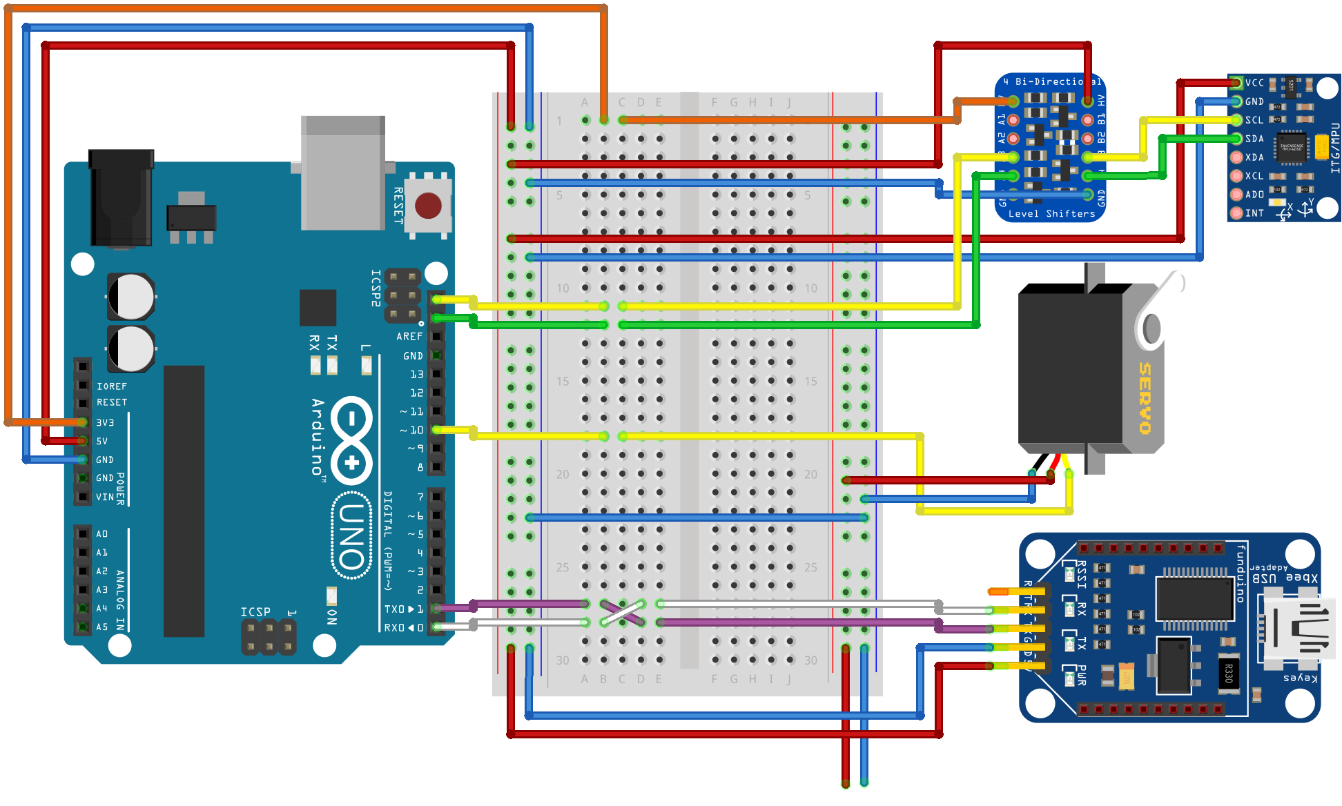
Hardware
- The microcontroller must be connected to the operator’s device to enable USART communication
- The servo must be connected to power and the microcontroller as shown in the diagram
- IMU (MPU-6050 or compatible MPU-9250) can be connected to the microcontroller as shown in the diagram
- The lidar must be connected to a stable power source and to the operator’s device
Software
On the microcontroller, the lidar-avr program must be flashed.
On the operator’s device, you need:
- lidar-tools/sync
- lidar-scan
Then you can proceed to configure lidar-tools/sync. All available program parameters should be adjusted using command line arguments. Their number can be large, so it’s convenient to prepare a script that will run lidar-tools/sync passing it appropriate parameters (like sync.ps1 located in the main lidar-tools project repository).
Parameters for lidar-tools/sync
| Parameter | Description | Notes |
|---|---|---|
| avrport | port through which communication with the microcontroller takes place | |
| avrbaud | baudrate used by the microcontroller for communication | default 19200 |
| lidarexe | path to the lidar-sync executable file | |
| lidarport | port through which communication with the lidar takes place | |
| lidarmode | lidar operating mode | 3 (indoor, default) or 4 (outdoor) |
| lidarpm | number of lidar revolutions per minute (RPM) | 200-1023, default 660 |
| servostep | single servo step in its units | |
| servodelay | time interval between servo steps in milliseconds | |
| servomin | minimum servo position in its units | default 1000 |
| servomax | maximum servo position in its units | default 3000 |
| servocalib | servo position for which the lidar plane will be in a position as parallel as possible to the ground | default 2500 |
| servostart | starting servo position for scanning | default 3000 |
| servounit | important value determined experimentally, which is used to convert servo unit to degrees: 1 servo unit = servounit ° | default about -0.047 |
| cloudrotation | all points lying on the plane scanned by the lidar will be rotated by cloudrotation radians | for prototype head: -π/4, (-0.785398) |
| acceluse | if true then takes IMU into account, if false then only requested servo positions | true or false |
Materials
Helper Software
Software that was created as an aid during work on the projects. These are simple programs/scripts that perform one task.